DC34 Challenge
DC34 HHV Challenge
HHV Technologies is now HHV Toys! We’re so excited for our upcoming release of our new line of toys. Come by and check out our demos: Furbrain, Furbtar, and Technik toys!
If you want to learn more about about the Furbrain, check out our magazine advert.
Schedule
Aug 7: 1000 to 1800 PT
Aug 8: 1000 to 1800 PT
Aug 9 @ 1200 PT: Awards given out at the presentation stage in the HHV/SSV
Rules
- This is a CTF for humans by humans; full AI solves are prohibited (there are other CTFs for that).
- USB port, SWD interfacing, and anything else labeled “orga” or “not in play” is off limits
- Do NOT apply more than 3.3V to any part of the CTF demo toys
- Replacement parts are available for the addon build, but it’ll cost 25 points per part
- If you use a part(s) from the HHV parts pile in place of a kitted part, show an HHV CTF organizer for a bonus 25 point per part replaced
Flag format is HHV{<Flag text>}
Furbrain Interfacer Assembly Instructions
Interfacer Assembly Instructions
In your interfacer kit, you have the following (amongst other things)
| Designator(s) | Part | Type |
|---|---|---|
| B1, B2, B3 | Tactile buttons | Through hole |
| D1, D2, D3, D4, D5 | Red LEDs | Through hole |
| D6, D7 | Green LEDs | Through hole |
| J1 | 2x3 header | Through hole |
| U1 | SN74HC595N shift register | Through hole |
| U2 | Attiny414 | Surface mount - SOIC-16 |
| C1, C2 | 0.1uF capacitors | Surface mount - 0805 |
| R1 | 10k Ohm resistor | Through hole |
| R2 | 1k Ohm resistors | Through hole |
| R3 | 4.7k Ohm resistor | Through hole |
| R4 | 22k Ohm resistor | Through hole |
| RN1, RN2 | 220 Ohm resistor arrays | Surface mount - 1206 array |
That seems like a lot, so let’s break it up to make it seem simpler. We’ll be building a button input voltage ladder (buttons and through hole resistors), an LED driver (SN74HC595N, color LEDs, resistor arrays), the brains (attiny414), and then YOU will build the IR transmitter and receiver!
You may assemble these parts in any order you’d like, but if you’re new to solder, we’d recommend you start with the through hold components (the parts that have leads that attach through plated holes in the PCB) first.
Button input
This circuit is all through hole components. First, let’s assemble the resistors. Find the R1 part (you can use the color bands to calculate the resistance) and bend the resistor leads to fit in the two holes to the east and west of the marked resistor square. It does not matter which lead goes in which hole, just make sure one lead goes into each of the two holes. Solder on the reverse side and then repeat for R2, R3, and R4.
For the buttons, push the leads through the 4 holes (they’ll sort of snap into place). Solder all four points on the reverse side to complete the connection.
LED driver
Starting with the through hole components, add U1 to the front of the PCB. Make sure the orientation is correct (half-moon imprint end facing south). For the LEDs, D1-D5 are the red LEDs. The longer lead is the anode (the positive side), it’ll solder into the square plated hole with the + above it, while the shorter lead (the cathode side) will solder into the circular hole.
The surface mount components are on the bottom side of the PCB. For the surface mount components, apply a little bit of solder to one of the PCB pads, then use tweezers to place the part onto the pads while heating the solder on the one pad to make the connection. Once the component is in place, add solder to the remaining pad(s). Start with C1, U1’s non-directional bypass capacitor. Next, add RN1 and RN2, 220 ohm currently limiting resistors for the LEDs (these are also non-directional).
The brains
First, add C2, the bypass capacitor for U2. Next, note the side of the Attiny414 that has circle/dimple in the casing. This is pin 1 and it should align with the white silkscreen dot to the north west side of the U2 pads. Like the other surface mount pads, add solder to one pad and then bring the Attiny414 to that pad to create the join. Finish up by soldering down the remaining pads.
Finally, add J1, the 2x3 header. the longer sides should be facing down when look at the top side (side with all the labeling).
Your interfacer should look like this
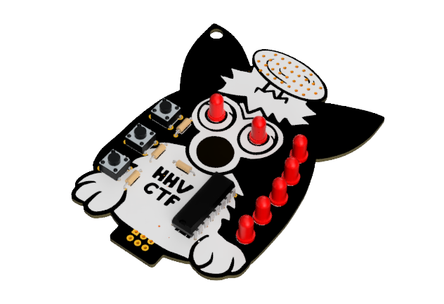
At this point you can come by the orga table and have your interfacer flashed with firmware (ooo blinky lights!).
IR transciever (your turn!)
You might be wondering about that top, antenna area now. For this last part you will be building the IR transmitter and receivers used to communicate with the Furbrain.
Here is the schematic for what you need to build: schematic
The interfacer provides
- 3.3V
- Ground
- IR TX pin
- IR RX pin.
You also have these additional parts in your kit for the circuit
| Designator(s) | Part | additional info |
|---|---|---|
| D8 | TSAL6200 IR LED | datasheet (larger, dark LED-looking thing) |
| Q1 | 2N3904 n-channel mosfet | datasheet |
| Q2 | TEFT4300 IR phototransistor | datasheet (smaller, dark LED-looking thing) |
| R90 | 1k Ohm resistors | |
| R91 | 100 Ohm resistor | |
| R92 | 47k Ohm resistor |
Pay attention to the long and short leads and labels! Some things that may help in the datasheets:
- E is for emitter
- C is for collector
You got this! And if anything is unclear, feel free to ask us questions.
Using your Furbrain Interfacer
B1: Feed the Furbrain
B2: Tickle the Furbrain
B3: Play a game of Rock, Paper, Scissors with Furbrain
During RPS, the buttons are as follows
B1: Rock
B2: Paper
B3: Scissors
Make sure your interfacer is close to the top of the Furbrain. In game mode, the LEDs will begin moving if a game is active, if not, it’ll time out after 5 seconds and you can try again. Make sure you’re still close, and in communication range, to tell your move to Furbrain. Beat it in a game of RPS to get a flag out of the CTF UART interface!