
DC30 Challenge
DC30 HHV Challenge
HHV Technologies, the inovation side of the Hardware Hacking Village, has been working hard on developing a new SOC, specifically for controlling electronic conference badges, called the HHVDC30. They provided us with a few “Badge” prototypes, and they’re particularly proud of their new SAO power control functionality. They say this new chip design and DRM implementation should be perfect, but here in the hacking department, we’re not so naive. Let’s find some bugs and prove those arrogrants engineers wrong?
A good place to start is probably looking through the datasheet for the HHVDC30. At the very least it’ll help you to understand what you’re up against.
PCBs for challenges donated by JLCPCB.
Write up
Warning: link contains spoilers
Challenges
SAO DRM Challenges
SAO DRM Challenge 1
The engineers wouldn’t give us an official copy of their first SAO. Fortunately, we were able to snap a photo of it (below). This SAO appears to use a hardware DRM. We were able to recreate the PCB design, but we only have 10k and 100 Ohm resistors. Using my microscope, I was able to read the following numbers on the resistors:
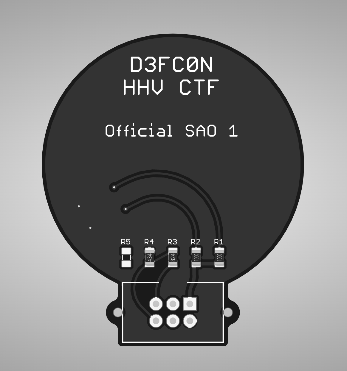
R1 - 1000
R2 - 1000
R3 - 824
R4 - 434
I think R1 and R2 are 100 Ohm resistors, but I don’t have any idea what R3 and R4 are. Maybe you can figure it out and figure out how we can fool this hardware DRM using only 10k Ohm resistors.
Note: there are two aspects to this challenge. Assembling the LED portion of the is SAO is meant to be a fun exercise so that participants have a keepsake from this CTF (it is not necessary to complete this challenge). Take a look at Assembly instructions for instructions for the LED portion of the assembly.
SAO DRM Challenge 1.5
As you’ve learned, the PCB for this challenge is missing something. Time to turn a mistake into a flag! If you’re able to assemble the LED portion of the badge, and have the LEDs light up, show an HHV volunteer and they’ll give you the flag.
SAO DRM Challenge 0
EDIT: Get a 3rd party SAO to pass the SAO DRM 1 check. We will not give parts for this, but you may be able to find some on the parts table.
Note: Depending on how impressive the SAO support is, there opportunity for more points. 200 points is just the baseline.
Hidden Badge Flags
I’ve heard through some back channels that the engineering team enjoys easter eggs. Do you think they’d really be so arrogant as to leave a few easter eggs in such a ground-breaking technological product? If you find anything like this in the HHVDC30, please let us know!
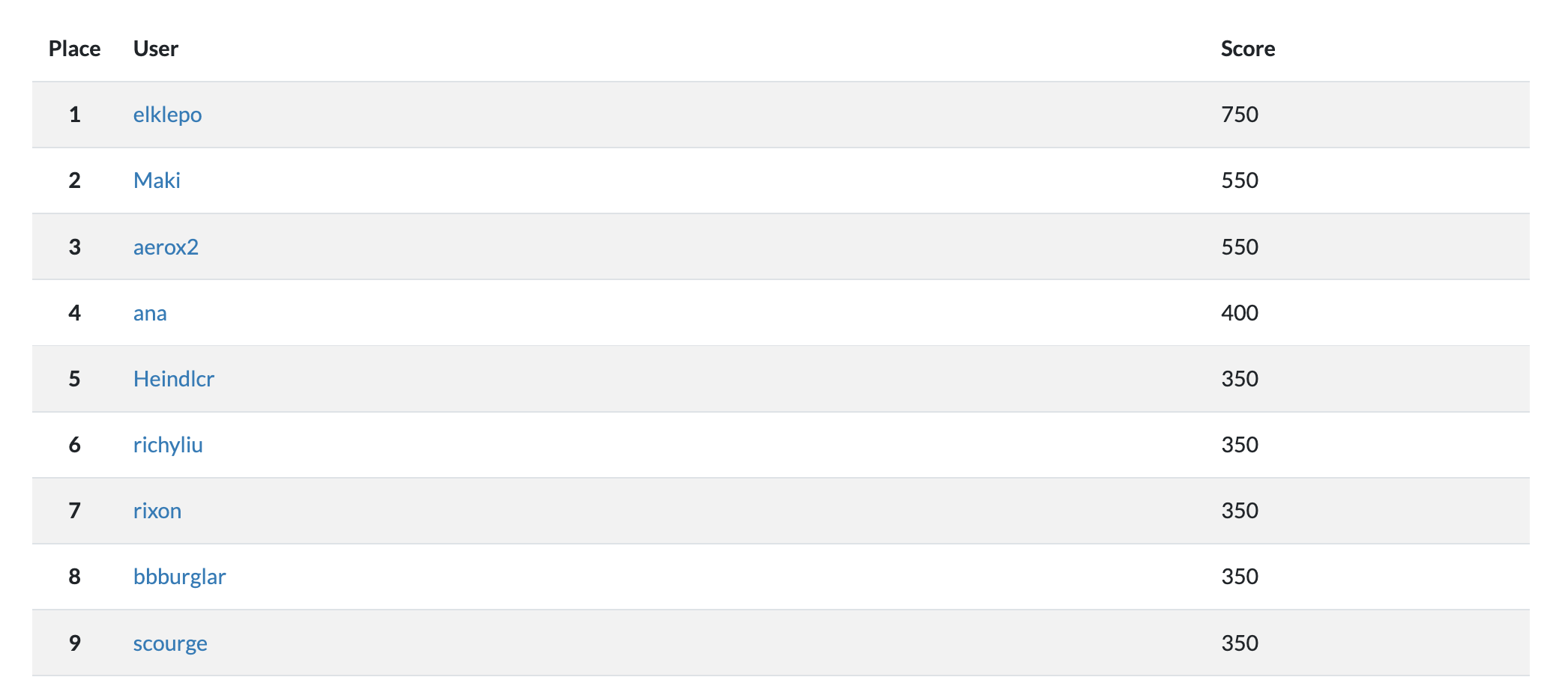
Awards
We were fortunate to award this year’s winner with a free admission to a future DEF CON. Congratulations to elklepo! We also awarded the top three winners with HHV CTF “Badges”, and a runner up received the PCB for the HHV CTF “Badge”.
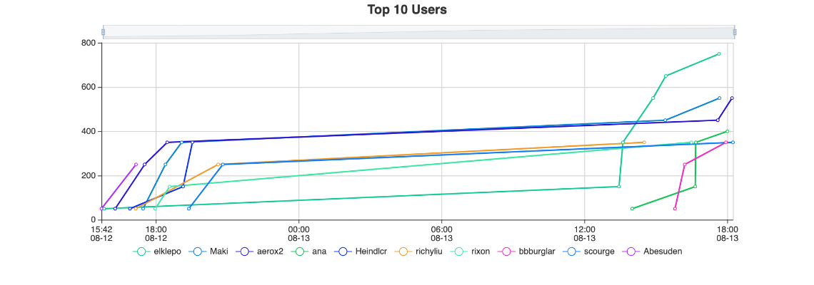
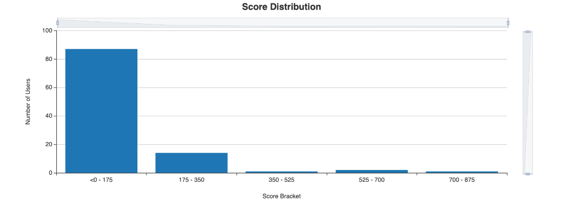
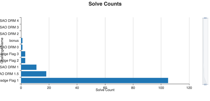
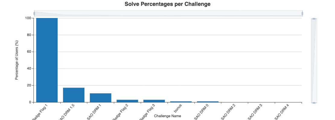
DEF CON 30 Stats
This was our biggest year yet! We had over 100 participants submit flags. Below are stats taken from CTFd. Note: SAO DRM 2-4 challenges were never made available.
SAO Assembly
Challenge 1 SAO Assembly
If you’d like your SAO to light up, you’re in the right place. Unfortunately, our team has already found one flaw in the SAO design, so the assembly process is a little more difficult than what I expect the HHV Technologies engineers planned.
In your SAO bag, you should have he following
- SAO header
- 2x LEDs
- 2x 100 Ohm resistors (marked with 1000)
- 5x 10k Ohm resistors (not needed in this assembly)
- some red jumper wire
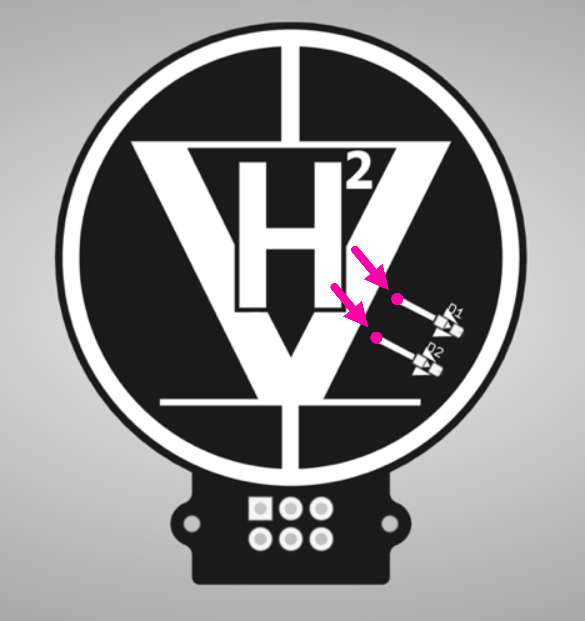
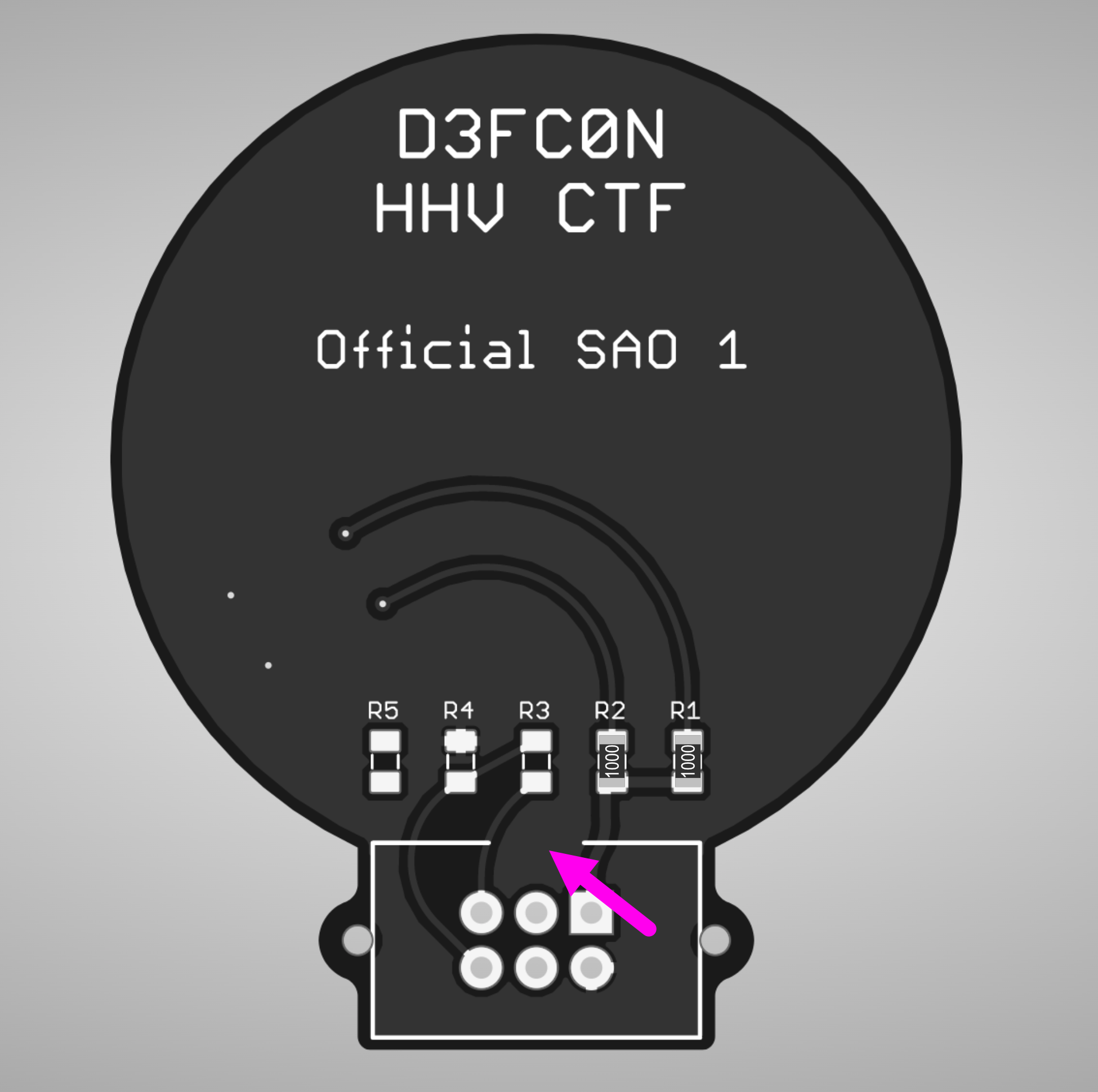
This first part will be the most difficult, since we need to fix a hardware design mistake. We will begin by removing the black soldermask from two copper vias on the front of the SAO (highlighted in pink below). The easiest way to remove the solder mask is either with an xacto (scratch it away gently) or a little sand paper (be careful not to remove too much of the surrounding soldermask)
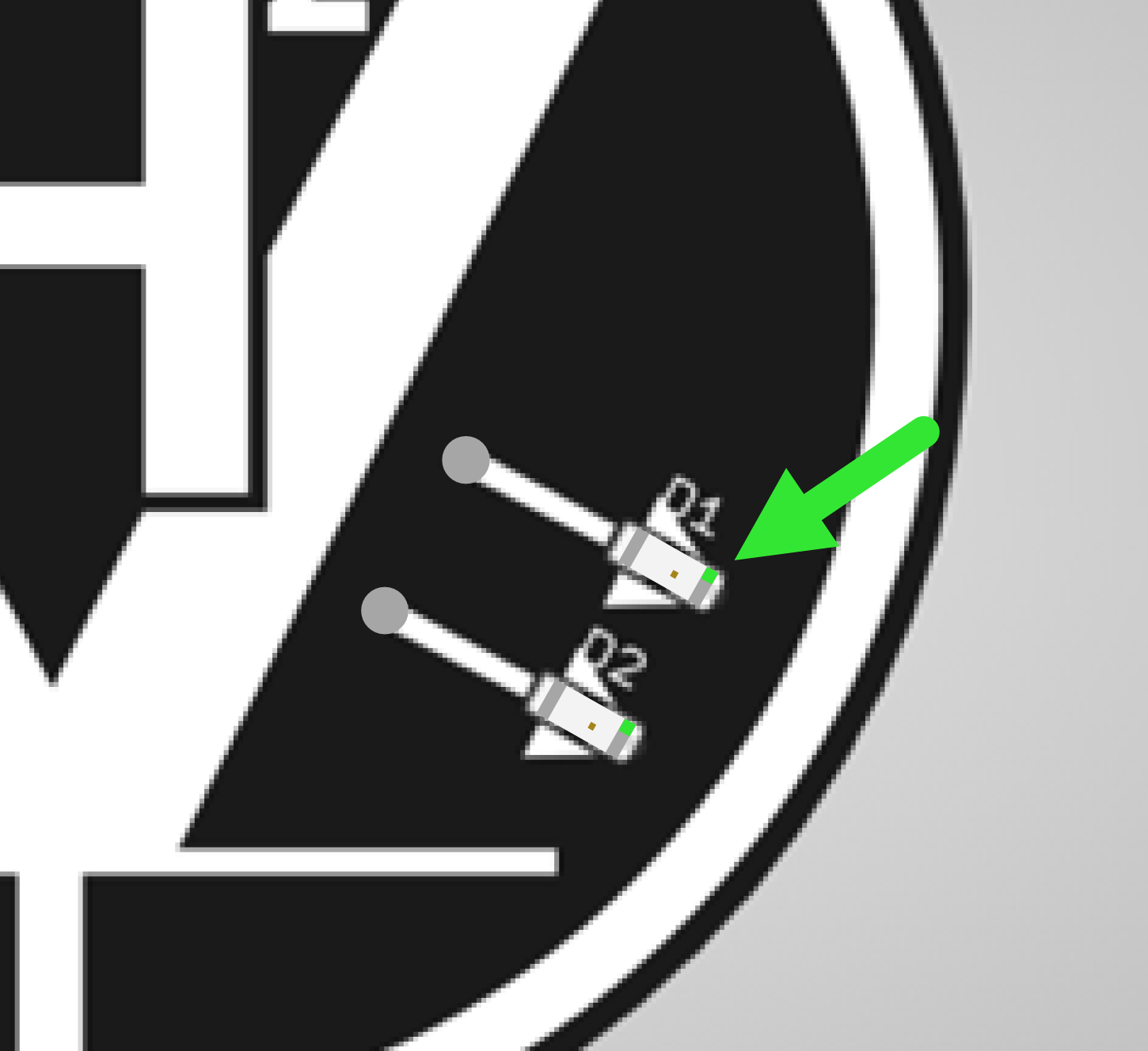
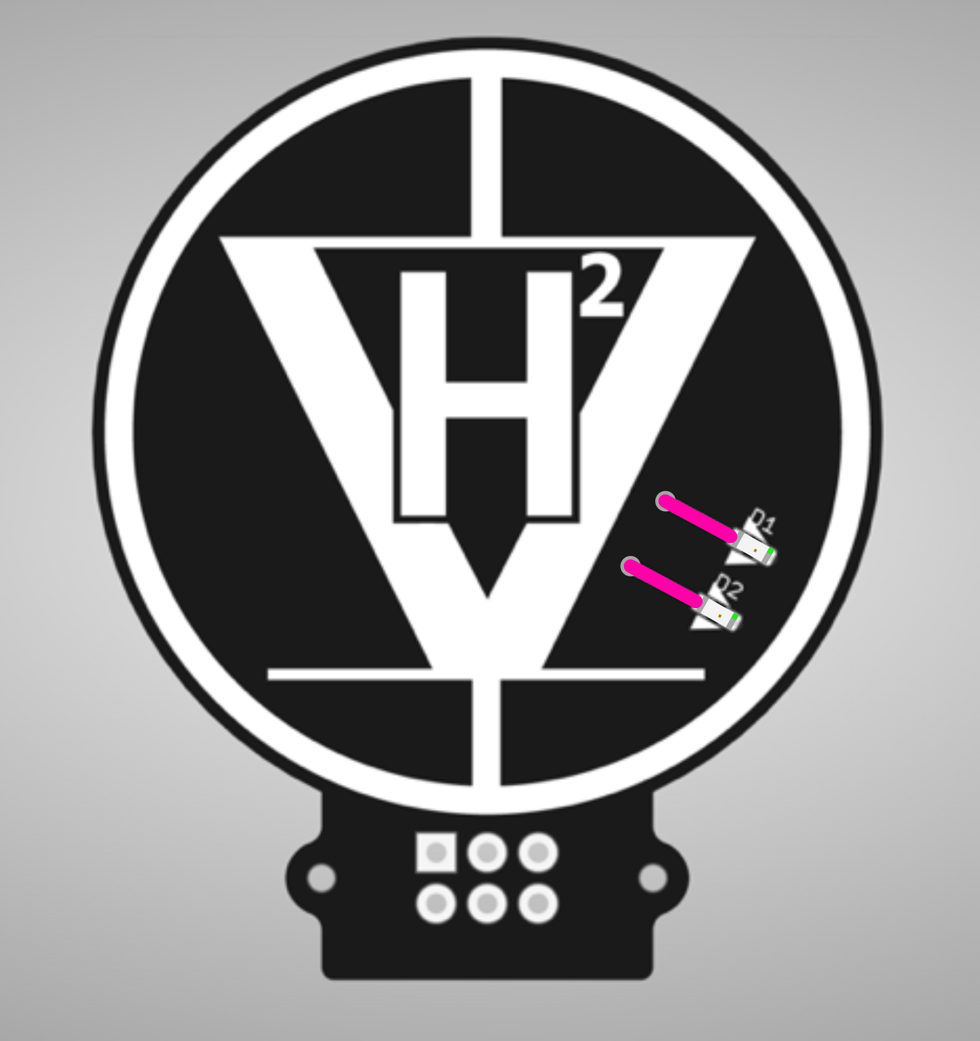
Now you can solder down the LEDs on the front pads denoted by D1 and D2. Make sure the LED is oriented in the correct direction or the LEDs will not turn on later. There is a green marking on one side of the top of the LED. Make sure that marking faces away from the center of the badge as shown below.
Now for the tricky part! You will need to use the red jumper wire to connect the exposed vias to the left side of the LEDs as depicted below (the pink line represents the red jumper wire). To solder the jumper wire, you will need to burn away some of the enamel coating on the end (a soldering iron with a ball of solder on the tip work well for this). Once the ends of the jumper wire are exposed and/or coated in solder, solder the jumper wire down using a pair of tweezers, or you may burn your fingers.
Woohoo! The bodge part is out of the way, and hopefully it’ll be smoother sailing for you now.
Flip the badge over and solder the 100 Ohm resistors on the R1 and R2 pads as shown below. Also you can solder on your SAO header, just make sure the orientation notch on the header matches the silkscreen on the badge (the notch should be facing the center of the badge).
Congratulations! You (hopefully) successfully assembled the LED portion of your add-on. If it lights up, go show rehr in the HHV and he’ll give you a flag ;D