
DC33 Challenge
DC33 HHV Challenge
HHV Technologies is proud to announce the release of the HHVDC33 and the SAO9000 — the next evolution in badge technology. The HHVDC33 is our most advanced badge-driving module to date, delivering unmatched LED performance, expanded control options, and enough horsepower to make your conference badge the envy of the room. Alongside it, we’re introducing the SAO9000 — a bold reimagining of the Shitty Add-On standard, featuring four additional pins for faster, richer communication between badges and addons, plus built-in orientation protection (because mistakes happen, especially at 3 AM). It’s a declaration that the future of badge hacking is brighter, louder, and far more expandable.
To celebrate the release of the HHVDC33 and the SAO9000, we have a few scaled up replicas of the HHVDC33 for DEF CON attendendees to see the beauty and design of this new IC. These replicas have all the functionality of the real chip, but in a package that’s as large as their capability. We also have addons you can build to try out the new SAO9000 port!
If you want to learn more about this amazing badge driver or the SAO9000 protocol, check out the datasheet for the HHVDC33.
Post Contest
Winners
| 1. Shadow Register | 2475 points |
| 2. The Council of Bob | 2400 points |
| 3. anish | 2100 points |
Writeup
Warning: link contains spoilers
Files and Challenges
Hardware and firmware build files have been uploaded to Github github.com/DCHHV/DC33-HHV-CTF
Challenge Text (no spoilers)
Schedule
Aug 8: 1300 to 1800 PT
Aug 9: 1000 to 1800 PT
Aug 10 @ 1200 PT: Awards given out at the presentation stage in the HHV/SSV
Rules
- Do NOT apply more than 3.3V to any part of the CTF demo badge or any Badgiimos
- Anything under the chip housing is off limits, no dumping the firmware
- Replacement parts are available for the addon build, but it’ll cost 25 points per part
- If you use a part(s) from the HHV parts pile in place of a kitted part, show an HHV CTF organizer for a bonus 25 point per part replaced
Flag format is HHV{<Flag text>}
Sponsors and Supporters
CTF Registration and Submission
Challenges
SAO9000 Addon Challenges
Build up an addon to try out the new SAO9000 standard! Build instuctions below. I’m not sure where this design came from, no way the engineering team would send us the same design they use for interfacing with the chip, right?
Note: You must have a non-zero score on the CTF board to receive an addon.
HHVDC33
Come play around with and experience some of the functionality of the HHVDC33! Use your SAO9000 addon to interface with the demo unit. There are fun features we’ve included in this special release unit like an embedded hall effect sensor, pre-programmed LED effects, and more! We unfortunately lost a few of the demo attachments, but don’t let that stop you from playing around and experience our new chip.
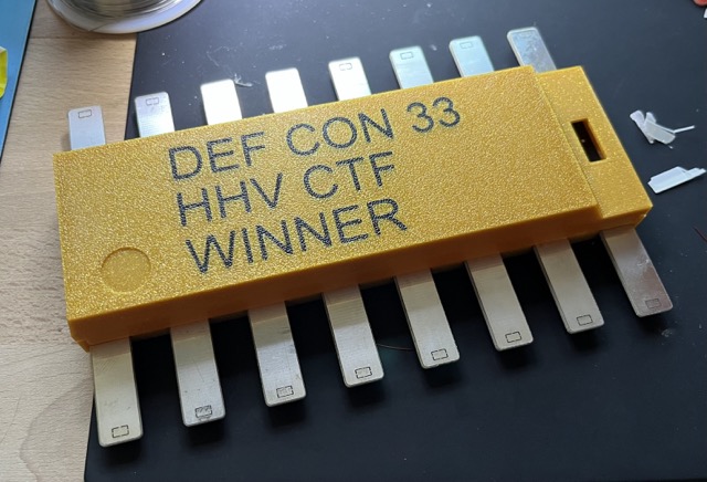
Awards
Winner gets the HHV Golden Chip
SAO9000 Addon Assembly Instructions
Addon Assembly Instructions
In your addon kit, you should have he following
- 1x 10k Ohm resistors (through hole)
- 1x 180 Ohm resistor (surface mount)
- 1x Orange surface mount LED (surface mount)
- 1x 2x3 header
- 1x 2x2 header
- 1x 1x6 header
- 1x PCB
I’m not sure why, but you should also have
- 3x 10k Ohm resistor (through hole)
- 1x 4.7k Ohm resistor (through hole)
- 3x 4.7k Ohm reistors (surface mount)
- 3x 1k Ohm reistors (surface mount)
- 3x 1N5817 diodes (through hole)
- 3x 2N2222A NPN transistors (through hole)
…maybe those parts used by the dev team?
You may assemble these parts in any order you’d like, but if you’re new to solder, we’d recommend you start with the through hold components (the parts that have leads that attach through plated holes in the PCB) first. find the R2 part and bend the resistor leads to fit in the two holes to the north and south of the marked resistor square. It does not matter which lead goes in which hole, just make sure one lead goes into each of the two holes.
For the headers, the 2x2 and the 2x3 the longest sides should be facing down when look at the top side (side with all the labeling).
Lastly, let’s assemble the surface mount LED and resistor. The 180 ohm resistor is non-directional and should be soldered onto the R1 pads. The LED is directional, so they will only work in one orientation. Don’t sweat though, you got this! The LED has a mark on one side. Make sure the mark matches up with the ‘k’ marker on the PCB. For soldering them down, apply a little bit of solder to one of the two pads then use tweazers to place the LED onto the pads while heating the solder on the pad. Once one side of the LED is soldered down, solder the other side. Repeat for the other two LEDs.
For the last part, the 6-pin header, solder the shorter, bent pins into the top side (labeled side) through holes so that the longer pins are running parrallel to the PCB on top.
To test if everything is working so far, plug the addon board into the demo unit of the badge, the LED should light up when it’s plugged in if everything is correct!
Your addon should look like this
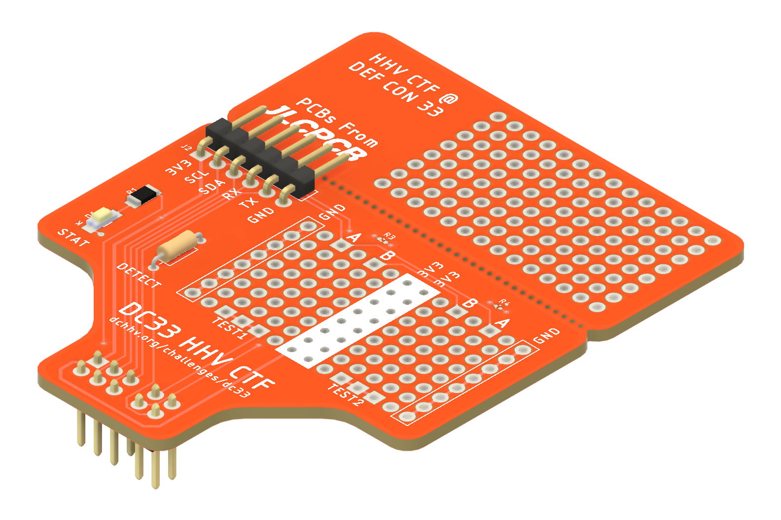
As for the remaining parts, I remember hearing something about 3 checks or tests the addon need to pass before enabling Dev Mode. If memory serves me well, I think the A and B pins are used to generate some binary outputs and Test 1 needs to receive OR logic and Test 2 needs to receive AND logic output. I can only guess the parts included with the addon kit are enough to do this. Oh! And the last test, Test3, I think it’s some sort modification to the addon detection pin, hopefully those small components don’t need to go on those small pads. Yikes!