
DC33 Challenge Writeup
DC33 HHV CTF Challenge Writeup
Ooo Pretty Lights!
Ooo Pretty Lights! is a series of challenges relating to pin 3 (GP1) of the HHVDC33. In the datasheet, GP1 is shown to have an extra feature of “WS2812B Driver”, and there’s mention of missing attachments for the demo unit in the challenge text. Those clues are meant to lead participants to probing the output of the pin. On the pin, they’ll see WS2812B data being transmitted on startup and whenever the led command is sent to the CLI.
Ooo Pretty Lights! 1
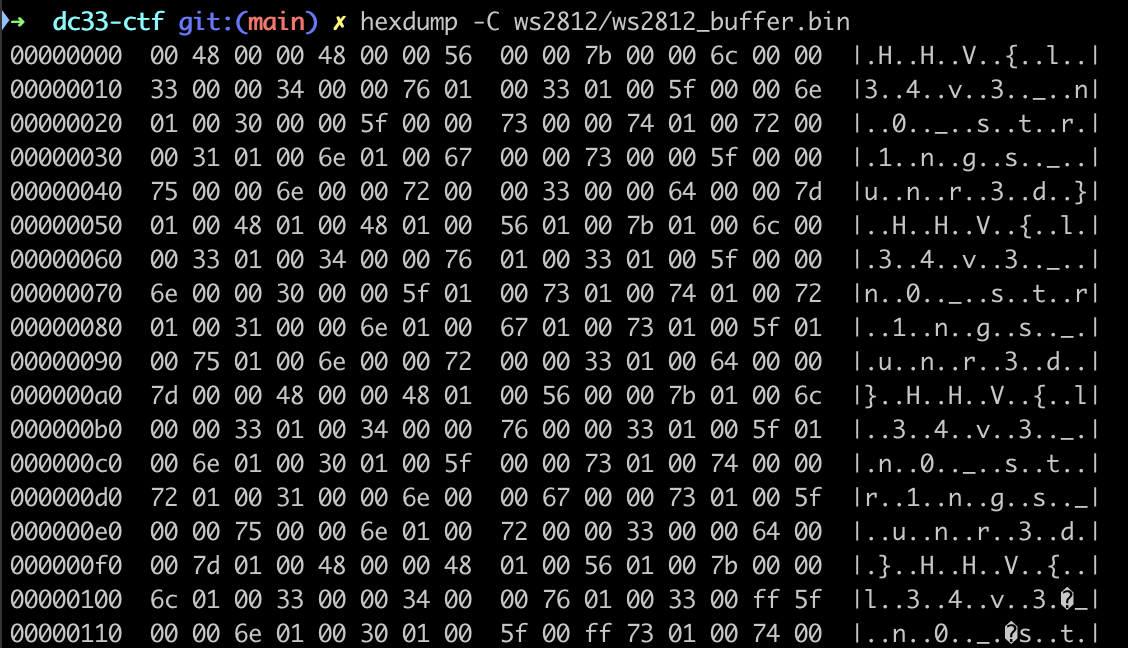
The first challenge uses the red channel of the WS2812B output stream. All red values are simply Ascii characters, so capture the WS2812B stream and output it as Ascii to get the flag HHV{l34v3_n0_str1ngs_unr3d}.
Ooo Pretty Lights! 2
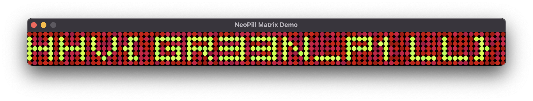
Pretty lights 2 uses the green channel of the WS2812B output stream. It does require rendering the stream in some way though (there are many ways to do, it testing we modified this script to take a WS2812B binary capture). Take the output, visualize it as a 90x7 grid to get the flag HHV{GR33N_P1LL}.
Ooo Pretty Lights! 3
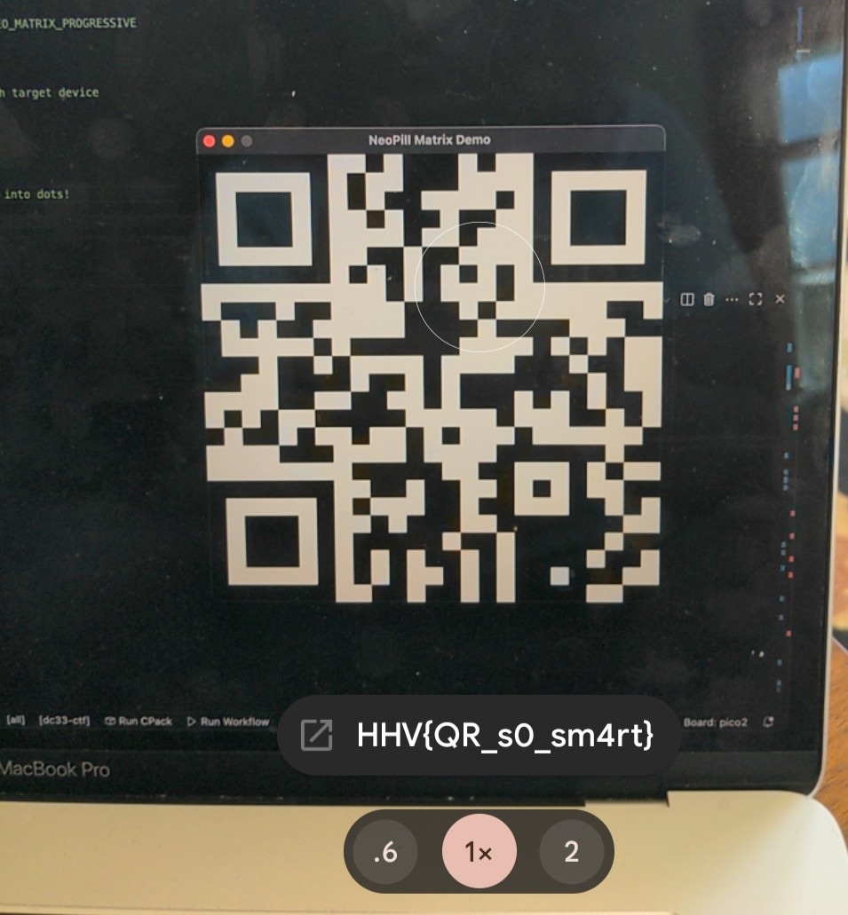
Pretty lights 3 uses the remaining blue channel of the WS2812B output stream. This challenge also requires some rendering, and then some additional work. The blue channel uses 0x01 and 0x00 to set pixel on and off, and when configured as a 25x25 grid, you get a QR code with the flag HHV{QR_s0_sm4rt}.
Resistance is thermal
The answer to this trivia question can be found on page 2-20 of the 1984 Motorola single chip microncontroller manual as 92°C. The flag is HHV{92}.
Note: the original question was “What is the thermal resistance junction to ambient in degrees Celsius per Watt for the MC6821 in a plastic A42 package?”. Coincidentally, and not understood by the organizers at the time, the answer is also 92.
Hello Moto
The answer to this trivia question is tough since there are many names associated with this tool, but the original is MICRObug. The flag is HHV{MICRObug}.
Demo Party 1
Read the fictional datasheet for the HHVDC33, flag is on page 4 as part of the high-level source current line of the table. The flag is HHV{source_current}.
Demo Party 2
One of the commands for the CLI is “hes”. This command checks the state of the embedded Hall Effect sensor in the HHVDC33 demo unit. When a magnet is present, the response from the CLI is “Testing HES… Present - HHV{h4ll_y3Ah!}”. The flag is HHV{h4ll_y3Ah!}.
Note: the organizers had a magnet you could use if you asked kindly.
Plugged In
Another CLI challenge. This is meant to be an easier flag to reward participants for getting the UART/CLI interface set up properly. Once the CLI is running, send the “info” command. The CLI will respond with information about the HHVDC33 demo unit along with the flag HHV{u4rt_d01ng_s0_gr43t}.
Addon Challenges
There are a series of challenges related to the addon participants can build. Three of the challenges are tests to build different analog circuits with the parts provided. There are multiple solutions that will work. Once a test is believed to be completed, contestants can then plug in their addon to an HHVDC33 demo unit and the unit will check the tests and output the pass/fail to the CLI along with the flag if the challenge was solved correctly.
Addon Test 1
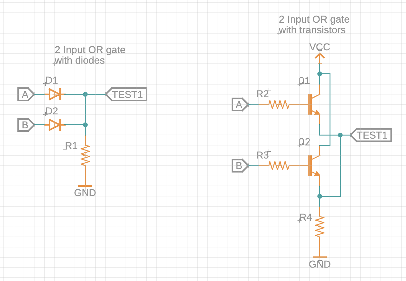
Build a logic OR gate with some of the parts provided. The intention is the participant cannot use diodes for both logic gates, nor can they use transistors for both logic gates, so one will use diodes and the other transistors (unless they dig components from the parts table). Below are the diode and transistor versions of an OR gate. Once the test passes, the CLI will give the flag HHV{L0G1C4L_DUD3}.
Addon Test 2
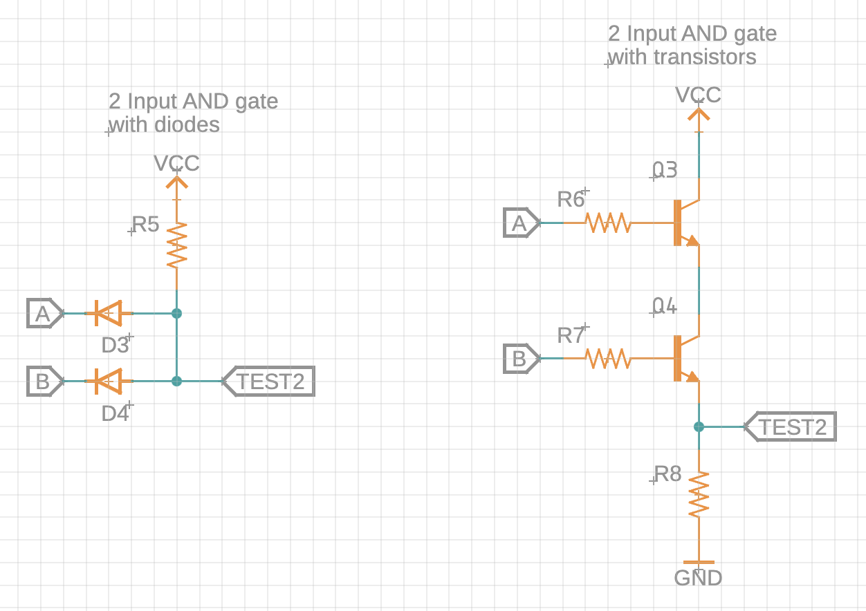
Using either diodes or transistors (different from what was used in test 1), build a logic AND gate as shown below. Once the test passes, the CLI will give the flag HHV{1T_T4K3S_2}.
Addon Test 3
Correctly solder R3 and R4 to get the flag, or discover the underlying voltage divider circuit and build the circuit with larger components. Once the test passes, the CLI will give the flag HHV{MY_3Y3S_HUR7}.
Feats of Strength
CTF organizers underestimated the strength it’d take to break the perf board away, so this was a silly challenge that could be solved by hand, but pliers made it easier with greater leverage.
Blinky Lights
Once the resistors R1 and R2 and the LED D1 were correctly soldered on, the addon LED would blink. The blinking could be decoded as Morse code using either a logic analyzer or by eye/following with tapping. The morse is decoded to HHVN0R3M0RSE, which will work as the flag or by adding curly brackets for HHV{N0R3M0RSE}.