
Converting UPS 2844 to stock Zebra LP-2844 firmware
by kbembedded
27 January 2019The Zebra 2844 is your bog standard no frills thermal label printer that was produced for more than 8 years. I cannot be sure of exactly how it went down, but I do believe that UPS would subsidize these printers re-branded as “UPS 2844.” Using their custom firmware would limit use to their tools and drivers (sort of, it’s complicated). It was in their interest to not let the Average Joe put the stock firmware on the device if they were giving them away or selling at a reduced price. This is how to restore a UPS 2844 to the stock firmware followed by a breakdown of the full thought process.
Overview of the 2844 thermal printer
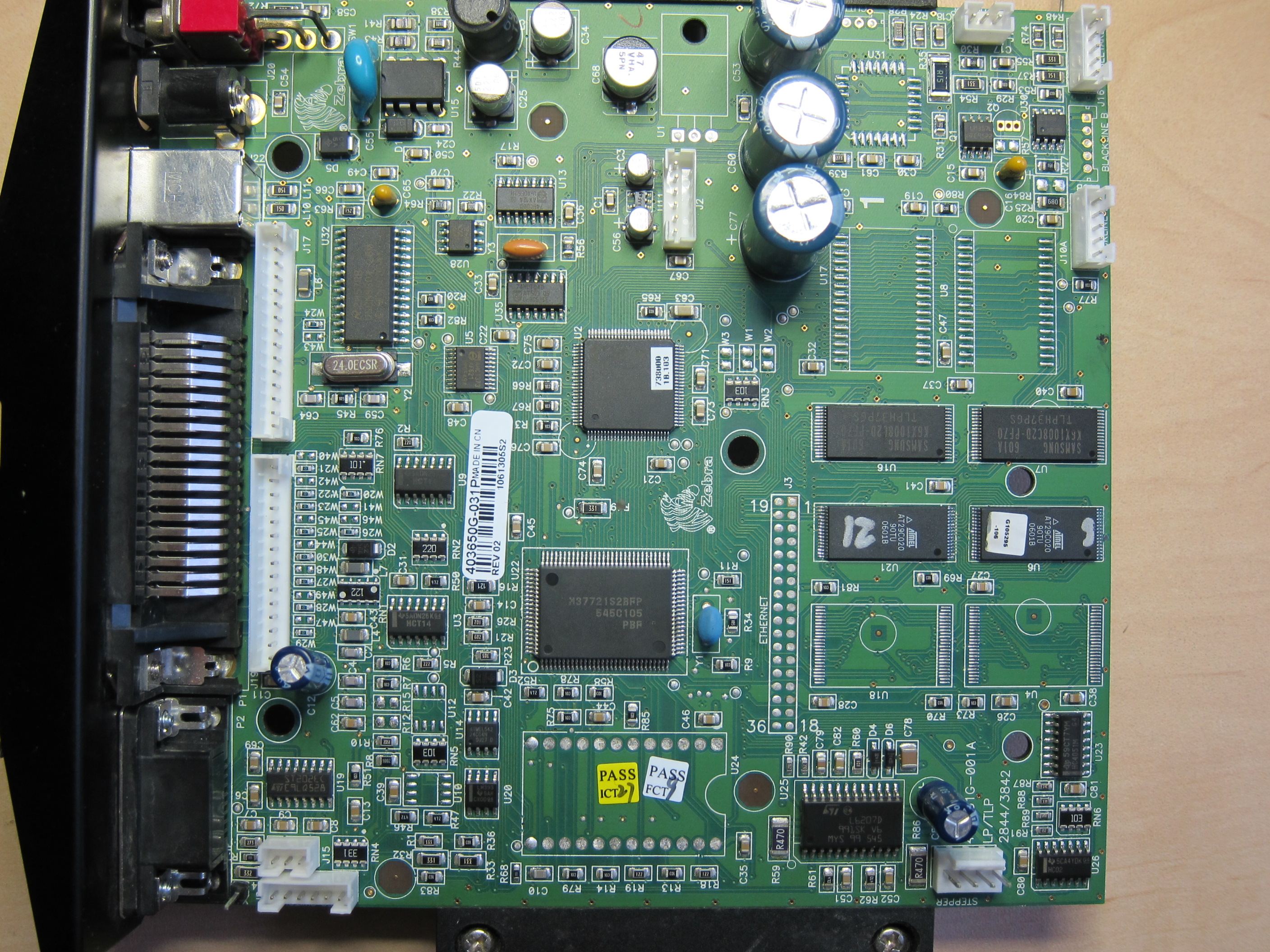
I’ve only ever had this one unit, I have no idea if multiple variants were produced, new PCB spins, etc. The printer itself has a USB, Parallel, and Serial port on the rear, and the PCB calls out a connection that somehow would integrate Ethernet. All of these interfaces use the EPL2 language (external link) in order to send commands to the printer. EPL2 is a mostly plaintext set of commands, with some of the arguments accepting binary data. For example, in order to just print some text, an EPL2 string that could be sent to the printer would look like A<X start pos in dots>,<Y start pos in dots>,<Text rotation>,<Font settings>,<X total text width multiplier>,<Y total text height multiplier>,<Invert text/background>,"Text to print"\r\n. This would render “Text to print” at the specified location on the page, in the selected font and size, scaled and rotated as desired.
The EPL2 language has barcode creation commands, direct graphical printing commands, supports custom fonts, and many other features that are handled by the LP-2844 internal microprocessor.
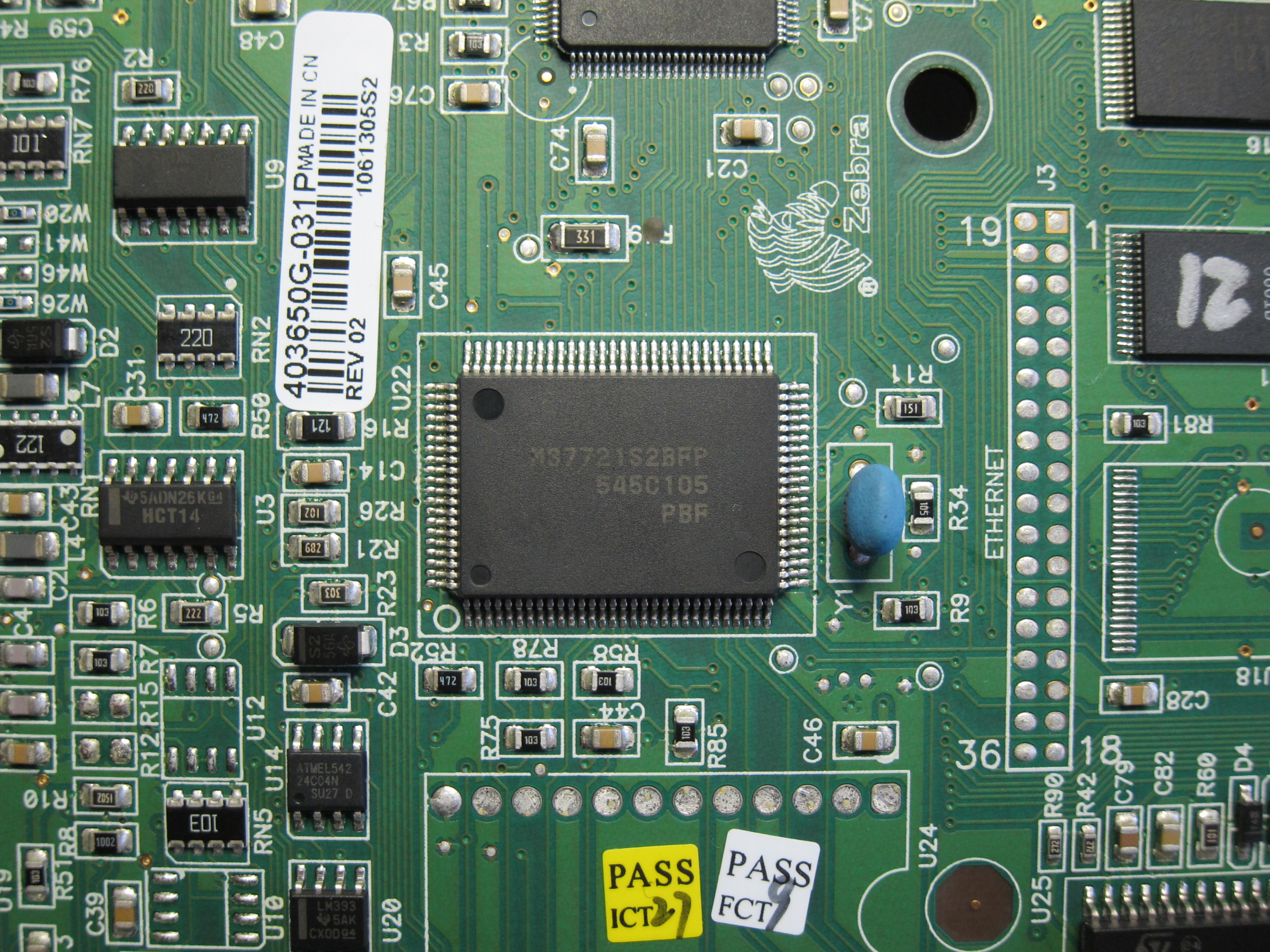
The 2844 is powered by a Renesas/Mitsubishi M37721S2BFP. The M37721S2BFP is a 16-bit microprocessor that can be run at up to 25 MHz. This microprocessor has no internal ROM and only 8 Kbits of internal RAM. All executable code is read from the external bus of the microprocessor. The microprocessor is able to address up to 16 MBytes in total, this includes the internal registers, the internal RAM, and the external address bus.
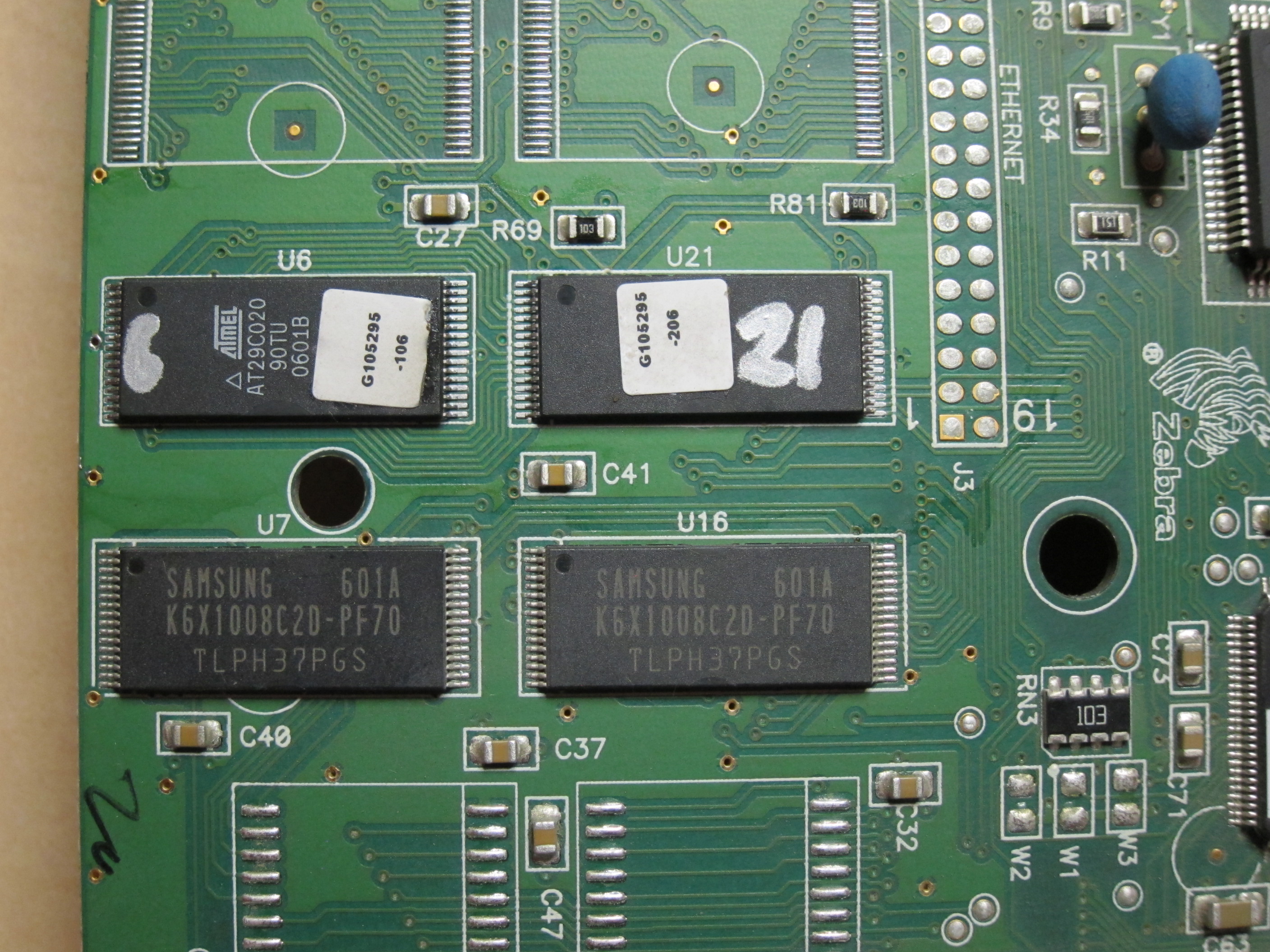
Additionally, the mainboard has 4 Mbits EEPROM-like non-volatile CMOS flash storage using two Atmel AT29C020. These are connected to the external microprocessor bus as a high and low byte. That is, each device is 8 bits wide; in order to allow the 16-bit microprocessor to fetch 16-bit instructions from these devices, they both have the address lines wired the same way, but one chip is connected to the upper 8-bits of the data lines while the other is connected to the lower 8-bits. These devices contain all of the microprocessor firmware, as well as other settings, custom fonts, and custom images.
There are 256 Kbits of Static RAM (SRAM) from Samsung that are also attached to the external microprocessor bus arranged in a high and low byte fashion like the flash storage. The SRAM is wired to be in a different address range than the flash devices so the microprocessor can access both RAM and code as needed.
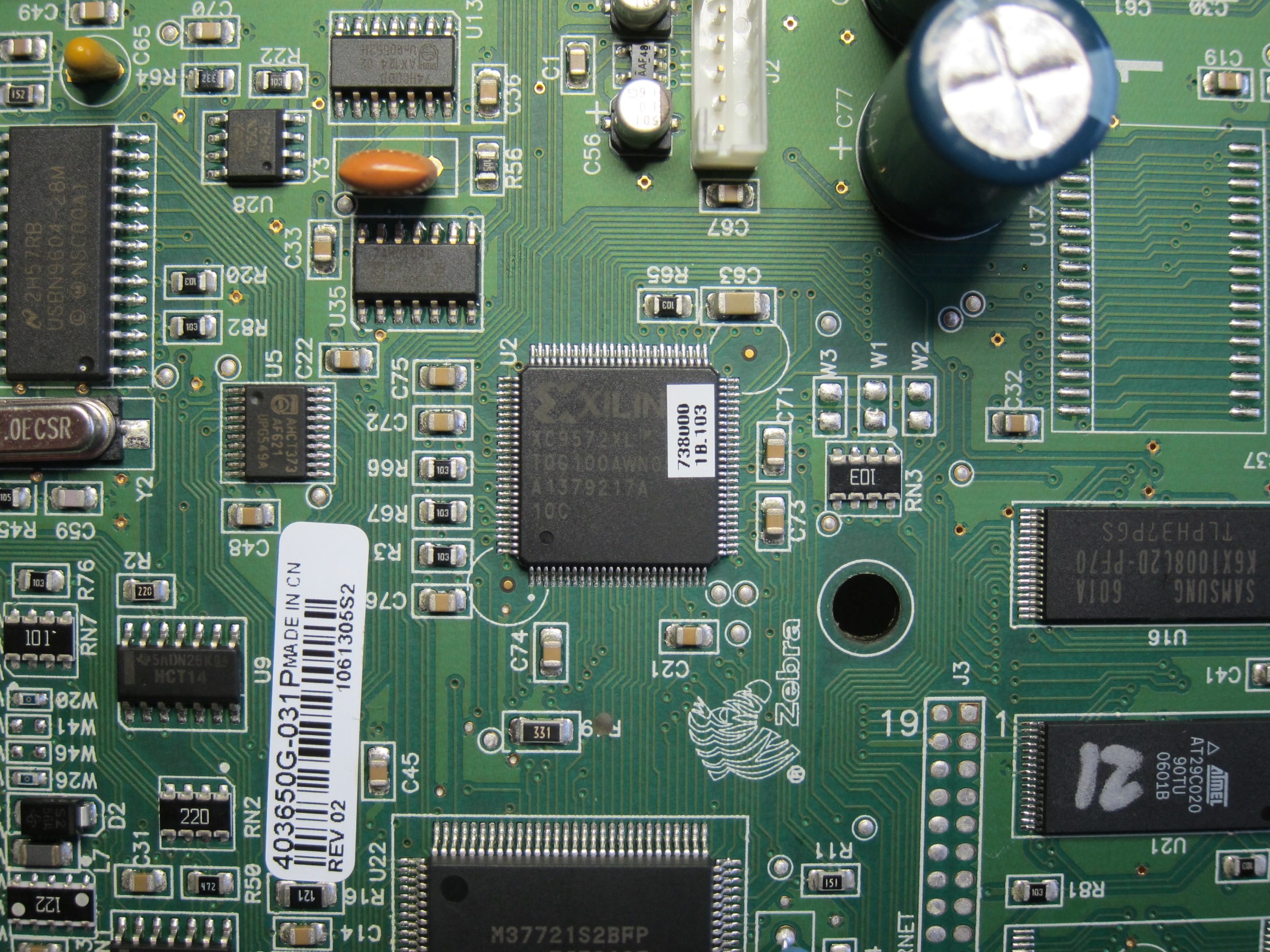
The last device of note is a Xilinx XC9572XL CPLD, presumably as glue logic. This would most likely be used to interface other logic on the mainboard to work with the microprocessor’s external parallel bus. There are other devices on the mainboard, a USB controller, stepper controller, thermal print head, and other misc logic that the microprocessor would need to communicate with. The exact purpose of the CPLD was not discovered, the above is pure assumption.
The “UPS 2844” firmware and drivers were designed to better integrate with the UPS shipping software. The labels created in the shipping software were not a standard format and could really only be printed on a UPS label printer or a 8.5” x 11” sheet of paper. It was not possible to output the created label to a PDF of the proper size to later print on an actual thermal label. It was possible to migrate away from the UPS specific software and use other carriers that could print through OS print dialogs, but it left much to be desired from the thermal printer itself. The standard LP-2844 drivers could be forced upon the printer, but this resulted in: mis-aligned prints, a mismatch between expected and actual label sizes that need to be resolved every power-up, and, just in general, wasted labels on a regular basis. My hope was that getting the latest stock firmware on the unit would resolve many of these issues.
The firmware files are binary blobs given freely by Zebra to update existing printers. In the case of the LP-2844, it is made up of undocumented EPL2 commands and binary data. Zebra gives a lot of warnings not to use the stock firmware files to update carrier specific units as it may result in inoperability. But, here at the HHV, inoperability means opportunity!
Updating the UPS 2844 to stock LP-2844
Attempts to use the Zebra Firmware Update utility to write a firmware update would show success, but the unit would still report the old version number. Mostly likely, the printer would receive and acknowledge the data from the utility but simply discard it rather than writing it to flash.
In order to modify the flash, it must be removed and written out of circuit. There are settings in flash outside of the executable code that the firmware update does not touch. This includes the serial number, downloaded fonts or graphics, and some other data that I did not fully analyze - but it does include the interrupt vector table (IVT) and what looks like some USB identification strings. Because of all of this, it is required to take a full dump of both of the flash ICs, apply the firmware update, write the new binaries to both flash ICs, and reinstall them in the unit. There may be a more efficient way of doing this, but, for now, it works as it is.
The stock firmware blob actually contains EPL2 instructions that the LP-2844 would interpret, followed by binary data that normally ends up being written to flash. There are two contiguous chunks that are written to flash, using the undocumented EPL2 command format DL<start>,<length>\r\n. Using this concept, the ‘patchzebra’ utility can apply this update to the flash dumps. I personally used a TL866/minipro to dump the flash ICs, but they are common enough devices that nearly any universal programmer would be able to read and write them.
git clone https://github.com/DCHHV/patch2844
cd patch2844
make
./patchzebra even_byte.bin odd_byte.bin update.prg output
Will output similar to the following:
Patching combined file starting at 0x2000, len 0xC000
Patching combined file starting at 0x10000, len 0x50000
The even_byte.bin and odd_byte.bin files are the dumps from the two 8-bit wide flash ICs. update.prg is the firmware update file from Zebra. Output is a prefix to use for output files. The application outputs output-combined.bin, output-patched.bin, even_byte.bin-patched.bin, and odd_byte.bin-patched.bin. The combined and patched flat files can be used for verification that the input files were combined and patched properly. The patched even and odd byte files can get written back to their respective flash ICs.
Below is a very rough flash table layout (from the perspective of the combined flat file):
| Range | Data |
|---|---|
| 0x00000 - 0x01FFF | Zeros (presumably mapped to another peripheral) |
| 0x02000 - 0x0DFFF | Firmware |
| 0x0E000 - 0x0FFCD | Unknown data |
| 0x0FFCE - 0x0FFFF | IVT for the microprocessor |
| 0x10000 - 0x5FFFF | More firmware |
| 0x60000 - 0x7FFFF | Serial number, configuration, customization, etc. |
The Hacker Process
Everyone walks down the path of hacking a little differently. It can be daunting when just starting out or even exploring a new classification of device. The following sections are more or less the path my brain took. I made incorrect assumptions and other mistakes along the way. Hopefully, showing how the dots were connected in this specific instance will be useful to someone else.
First Attempt
I started this late one evening when my internet was down. The UPS 2844 was pulled apart and analyzed without any online resources. It was not a hindrance, but it was definitely unwise to not have datasheets available. To me, it looked like there was a pair EEPROMs (close, they are actually CMOS flash) and a pair of NAND flash devices (wrong, they are SRAM). I labeled, desoldered, and dumped the CMOS flash devices using a TL866/minipro.
The TL866 (external link) is a low cost universal programmer. It has a single USB interface that connects to a Windows application supplied by the vender. There is also a third-party Linux software tool to interface with it that is purely command line. The device touts supporting “13000+ devices”, which is true, but it’s mostly due to the fact that so many devices all follow a similar standard. For example, the AT24 style of I2C EEPROM has hundreds of total size variants, manufacturer variants, and a handful of different packages. Each one of these is counted toward the full supported device list, but they are all handled by the same configuration.
Side note: The stock Zero Insertion Force (ZIF) sockets included with most of the TL866 bundles that can be purchased online are TERRIBLE; either use higher grade connectors or read a single device multiple times to ensure that the data read is exactly what is on the chip.
An EPL2 command exists that tells the LP-2844 to print a configuration page. The UPS 2844 would print the string “UKQ1935 UPS V4.51” as the first line of this configuration page. A similar string existed in the firmware update file from Zebra, UKQ1935 ... V4.70.1A located immediately after the header at the start of the file. It was a reasonable assumption to guess that UKQ1935 would exist in the firmware on the unit and it could be used to identify start of firmware. It was also reasonable to assume that nearly all of the text printed on the configuration page exists in the firmware as well.
I was concerned that the flash devices were just configuration data. It is possible to store settings, fonts, and images in the LP-2844. I could see various ASCII strings in the dumps of both devices but they were not always complete strings. There were instances of the full English alphabet, contiguous sections of upper-case letters, and various sequences of numbers. Unfortunately, none of them matched up with the configuration string above or any other strings I presumed were in the firmware. This lead me to believe these flash devices were just a dead end.
I soldered the two flash ICs back, re-assembled the unit, and decided to call it quits. In parallel with this, I picked up a second LP-2844 for cheap after confirming it was an official Zebra brand. I figured having a proper spare would get me a functional printer in either case.
Takeaways
- If you are removing any parts, make sure to note where they came from! A paint pen is a great way to accomplish this. In the photos above of the flash devices, there are markings that match up with their reference designator on the PCB.
- Having resources available is invaluable when taking things apart. It is difficult to identify every part based on form factor and part numbers just from memory.
- Notice that there was zero attempt to trace any of the circuit out. Assumptions can be made, but always remember to follow the mantra, “trust but verify”, even when it comes to your own assumptions. Taking the time to do this would have likely got me to the point of the second attempt sooner by seeing that the flash devices share address but not data pins.
Second Attempt
Laying in bed some nights later, I suddenly made a connection. The string UKQ1935 that was expected to be in flash actually WAS there, but it alternated between flash devices. That is, one dump contained UQ95 while in the other was K13. Looking at one flash dump and then the other resulted in missing this detail originally. This meant the flash ICs were arranged as a high and low byte on the data bus with shared address lines.
I browsed through the datasheets of all of the key components. The flash ICs that were dumped are 8-bit CMOS based flash devices. The microprocessor was found to have no internal ROM and a small amount of RAM. And the other set of ICs on the mainboard were in fact SRAM.
In my possession was a plain binary blob from Zebra of the latest firmware, dumps of what is the only non-volatile storage in the whole device, and nothing better to do the rest of the evening. But before any other manipulation was done, a copy of the original dumps were made and their hashes saved as well.
Spoiler alert I don’t get it working this attempt. I’ll spare the details and commands used here since they were ultimately useless.
The flash dumps both had a block of 0x00 data from address range 0x0 through 0xFFF. Starting at 0x1000 was the UKQ1935 string. This same string was near the start of the firmware update file, preceded by a short header. I chopped the header off of the firmware update file and split it in two; every other byte in to separate files to match the high and low byte flash devices.
The split firmware update files are the same length and this was used to determine how much space they would take up in the flash devices. The flash dumps had valid data starting at 0x1000 through around 0x28000. This range of data was enough to accept the firmware update written directly to it. After this range is a block of 0x00 data followed by sparse data, presumed to be configuration, serial number, etc. near the end of the address space. Each flash IC is 0x40000 bytes in length for a total storage of 0x80000 bytes or 512 Kbyte.
The necessary area of data was zeroed out in each flash dump followed by writing the correct half of the firmware update file. The resulting updated flash binaries were manually verified by looking at them side by side with the original flash dumps using ‘hexedit’ and a couple of terminals. Everything looked like it was in the right place.
The updated flash binaries were written to each IC and verified multiple times to ensure the data was correctly written. Everything was soldered back down but nothing happened when the power was applied. No USB devices appeared and the LED on the unit did not turn on. Nothing at all.
Takeaways
- This process was overcomplicated. I manually used
ddand other command line tools to do the zeroing of the dumps, splitting the firmware update file in two, and writing the updated firmware files to the flash dumps. - I made a grave assumption above. Headers usually exist on files for a reason, but it was plaintext and didn’t make much sense. I knew the firmware started with a very specific string, which this header did not match, and I deemed the header useless because of that.
- When working with manipulating data, always retain a golden copy with its known hash.
Final Attempt
At this point I made another pot of tea, deleted the patched binaries, and started all over. I went back to the firmware update file, thinking maybe the header actually was a clue. Take a moment and think about it:
DI2Y\r\nDS2\r\nDL2000,C000\r\n
They are three separate EPL2 commands, all of which were undocumented in the EPL2 manuals I’ve come across. That last one looks awfully interesting, though. Perhaps “DL” means DownLoad followed by “<start>,<length>”? What follows the “\n” after the “DL” command in the firmware update file is precisely 0xC000 bytes of data. Using this concept, it would mean that the start location is 0x2000 with a length of 0xC000. Remember how, prior to that, I said the flash dumps started at 0x1000? If you combine the high and low byte files in to a single flat file, that location turns in to 0x2000. Immediately after 0xC000 bytes of data in the firmware update file is another DL command, DL10000,50000, followed by 0x50000 more bytes, ending exactly at the end of the file.
That means my previous attempt failed for a number of reasons. Even though the commands in the header were removed, the second “DL” command was written to flash. Additionally, there is a gap of data that the “DL” commands do not touch, 0xE000 - 0xFFFF. The microprocessor interrupt vector table (IVT) is located between 0xFFCE and 0xFFFF. That range was clobbered by the first attempt as well.
The path forward is clear: write those two firmware sections provided in the firmware update file to where they need to go in the flash devices and hope that the section in the middle is still compatible with the stock firmware. If not, we have no idea what needs to go in the middle there without a working stock unit. The biggest concern is the IVT block. If any of those point to the wrong locations, the result could be anything from a simple failure to boot, all the way to overheating of the thermal transfer unit that could potentially set fire to the whole thing.
The IVT is important because it must exactly align with firmware functions for interrupt servicing. The IVT is essentially a lookup table of addresses for interrupt handling code in the firmware. When an interrupt occurs, the microprocessor will set the program counter to the specific location in the IVT for the requested interrupt. The IVT location contains a jump instruction which will immediately jump to the proper interrupt handling function. This is most critical for power-on as one of the interrupts for the microprocessor occurs after a reset of any kind. When the microprocessor is unreset after power on, the program counter points to the reset interrupt location in the IVT. This will then jump to the start of the actual firmware for the microprocessor. Other interrupts are for DMA, UART activity, timers, WDT, ADC completion, divide by zero error, reset, and external interrupt pins.
Since the firmware update file did not touch the IVT, it could be reasonably assumed that all firmware versions are compatible with the same IVT layout. There was a concern that the UPS firmware is different enough than any of the stock firmware versions that this IVT would be different. It could also be possible that some firmware updates would update the IVT as well with another “DL” command in the update file. However, this was not a large concern because Zebra made no claims that firmware could not be updated from any arbitrary version to the latest. This would mean that, to allow updating to the latest from any firmware version, the IVT must be compatible with all firmware versions.
I gave up on using command line tools. I pulled out my dev machine and quickly wrote some code with the following goals:
- Combine the two flash dumps in to a single file instead of attempting to split the firmware update file. Make two copies of this flat file, one for a golden combined image, and the other to patch with the firmware update file.
- Parse through the firmware update file looking for valid “DL” commands. This parsing would simply look for “DL” followed by a number, then a comma, then another number, then a newline. No bounds checking is done on the numbers - which, in retrospect, would have been a good idea.
- Write the firmware update byte stream starting at <start>, through <length>, to the combined flash dump file made in Step 1.
- Split the patched flash dump file back in to two individual files, one for the high and the other for the low bytes.
I still resorted to manually verifying the original flash dumps vs the patched files by looking at them side by side in ‘hexedit’. This was faster than trying to write out code for that as well.
The two flash ICs were desoldered from the mainboard for a third time, patched binaries written to them, and then soldered back in place.
Success! The LED lit up, the stepper motor clicked, and my computer told me a true “Zebra LP-2844” was now plugged in via USB. I sent it a “factory reset” command to remove as much of the remaining UPS configuration as possible. Immediately, I saw better prints with no hassle setting it up or modifying the configuration.
The printed configuration page now output “UKQ1935 V4.70.1A” on the first line. I couldn’t tell you what all of the firmware differences were, but going from “UPS V4.51” to “V4.70.1A” made the LP-2844 instantly more compatible with the stock drivers and the Zebra tools.
Takeaways
- Disassembly of the firmware update file may or may not have been useful from the start. It could have choked on the header originally and also pointed out the second DL instruction. But, it is also possible that a disassembler would have simply interpreted the commands as binary data, potentially obfuscating it more.
- When doing operations like this with repeated flashing of non-volatile storage, it might be best to invest in a solder down socket, though I’m not sure if TSSOP-32 sockets that solder to a TSSOP-32 footprint exist. I know they are available for a SOIC-8 package, for example, which comes in handy for AT24/AT25 parts.