
DC26 HHV Challenge Write-up
by mediumrehr
02 October 2018Thank you to everyone who participated, or is still participating, in this year’s challenge. This was my first year creating and running the HHV challenge, and as a result, I’ve learned a lot and I hope to bring it even better next year! Huge shout out to Chris Dubsky for being the first (and only) person to solve the challenge at DEF CON. If you weren’t able to participate, but still want to, the files are available on our Github. SPOILER ALERT Below is a write-up of the challenges and solutions. Don’t read past this point if you are still attempting (or want to attempt) the challenges without help/solutions.
Pre challenge
Before starting the challenges, it’s important to identify the 4-pin header on the top left of the board. This is the UART interface that is used to transmit the flags once they are unlocked. It also plays a role in solving part 1.
Part 1: Cracking the Passcode
There are a few ways to approach this problem. The intended way of solving the challenge is to perform a side-channel attack, but it is also possible to brute-force the passcode (there wasn’t anything preventing this) since there are only 65536 possible combinations.
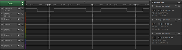
Using a logic analyzer and calculating the time delay between when a button is reported via UART and when the LED illuminates as feedback from a press, it’s possible to deduce whether or not a passcode entry was correct (as long as the prior entries were correct). The image below shows three button presses; the first is correct and there is a 20 ms delay between the UART (channel 2 in the image) report and the LED flashing (channel 3 in the image). The second button press is incorrect, resulting in a much shorter delay between report and flash. The third press will result in a short delay regardless or correctness since the system is designed to ignore following inputs once an incorrect passcode button press is entered.
The correct passcode is 14431212, and once it is entered, the middle LED will turn on and the flag “h3y_wh4ts_t3h_p4ssw0rd?” will be transmitted via the UART interface.
Part 2: Memory Manipulation
The second challenge utilizes the 24LC256 EEPROM. The microcontoller checks a specific address of the EEPROM on start-up, and if that address is set to a specific value, it will pass the challenge 2 check, turn on the bottom green LED, and output the flag via UART. There are two ways to start this challenge, either sniff the I²C lines running to the EEPROM to notice that the attiny is checking address 0x5A for a value on startup, or skip that step and dump the EEPROM. Dumping the EEPROM and entering the values into a hex to ascii converter will reveal the string “set address 0x5A to 0x26” starting at address 0x3.
There are two ways to go from here, you can either rewrite the EEPROM so that address 0x5A is set to 0x26, or you can disconnect the I²C lines from the EEPROM and create a device that spoofs the EEPROM interaction. The former route requires bridging the jumper (to the bottom right of the passcode buttons), disconnecting the write protect pin of the EEPROM. It’s pulled high by default, but bridging that jumper pulls the pin low, disabling write protection and allowing the EEPROM to be changed.
Disconnecting the I²C lines from the EEPROM and connecting them to a new device that spoofs the interaction is also a way to pass this challenge. Using a microcontroller, you can set it up as an I²C slave that listens for requests on address 0x5A. When it does, respond with the value 0x26, and that will pass that check, resulting in the flag “0h_1_r3m3mb3r_n0w!” being transmitted via the UART interface and the bottom green LED illuminating.